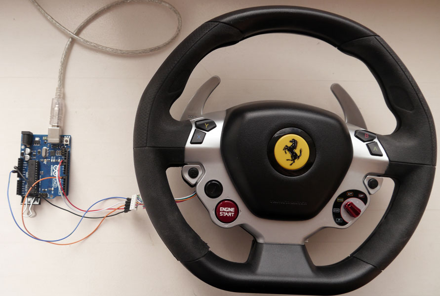
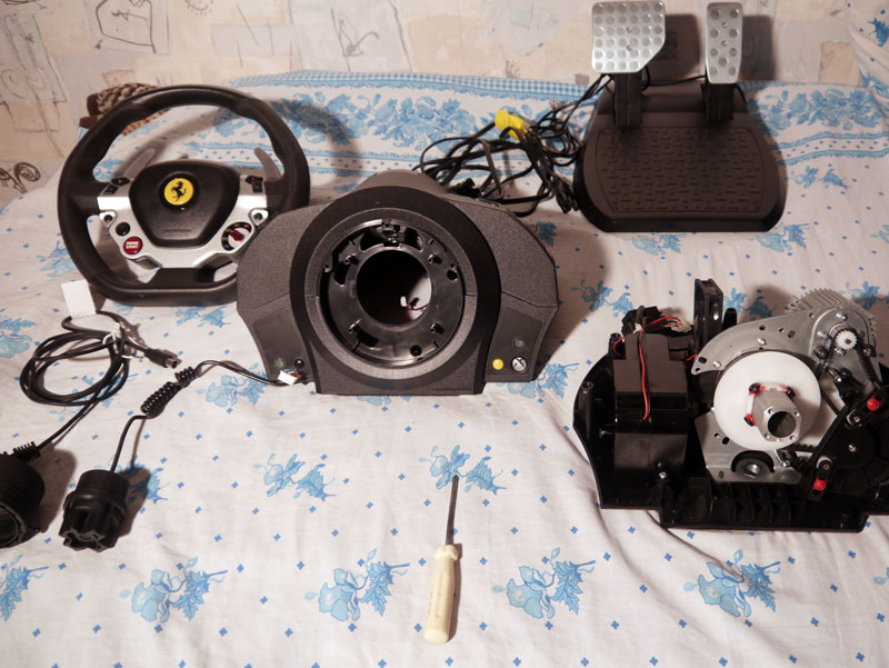
Here’s a Thrustmaster TX Racing wheel (Force Feedback TX base + Ferrari 458 Italia replica wheel). I got it broken, and because of the fact it required tear down and repair anyways (fixed already), I decided to play with electronics a bit more, connecting different wheel parts to Arduino board and reverse-engineering wheelbase-to-wheel wiring and protocol. Let’s take a look?
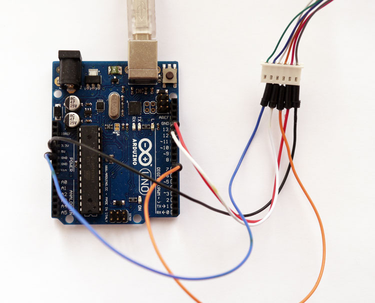
In part 1 we’ll be connecting 458 Italia wheel to Arduino Uno – and will try to read button presses from it – to understand how the wheel sends bytes of data to a wheelbase (to Arduino Uno in our case).
Having this done, in part 2 we’ll be connecting Arduino Uno to a wheelbase, trying to emulate button presses. My aim is to replace a plastic 458 wheel with something more realistic – quick-release + real racing wheel, 34-36cm in diameter, with a custom set of buttons controlled by Arduino (Arduino Nano, Mini Pro, Micro or just atmega8 mcu on a custom made board).
What’s inside: let’s guess
Before we start the tear down, let’s count the buttons. I can see 17 of them (13 buttons including paddle shifters + 4 buttons for red joystick – down+up+left+right). Each button can be either released or pressed (1 or 0 in computer logic) – this means we need 17 bits to store/transfer the wheel state (assuming there’s no coding/compression). Bits are usually packed into bytes before any transfer – so I suppose the wheel stores and transfers 3 bytes of data (3 x 8 = 24 bits, 17 used for buttons + 7 not used/reserved/encode the wheel ID/etc…). Time to take a screwdriver and find out if we were right.
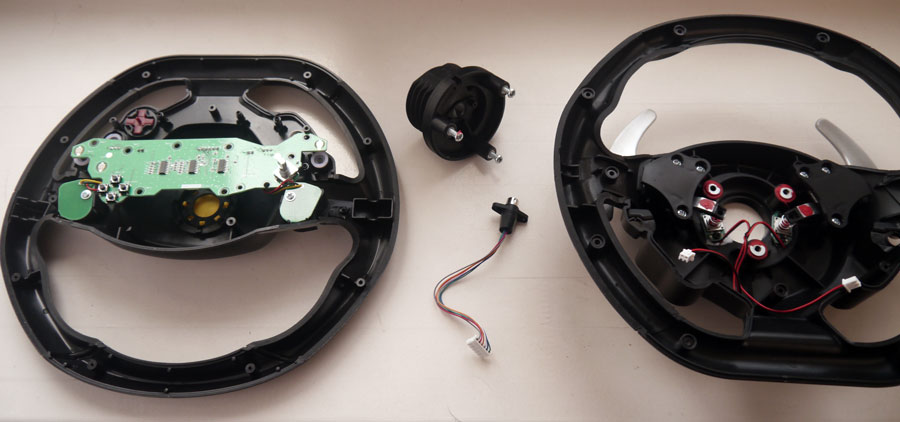
What’s inside: tear down
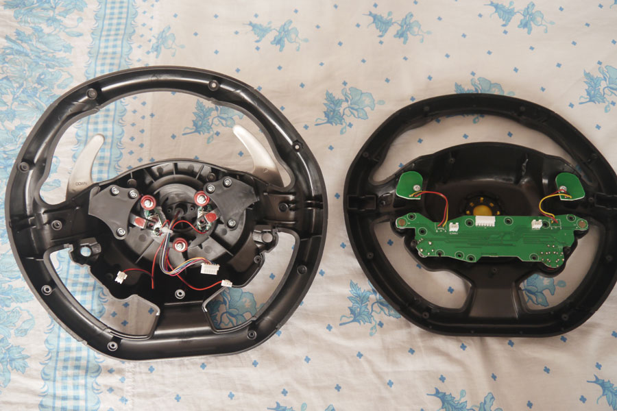
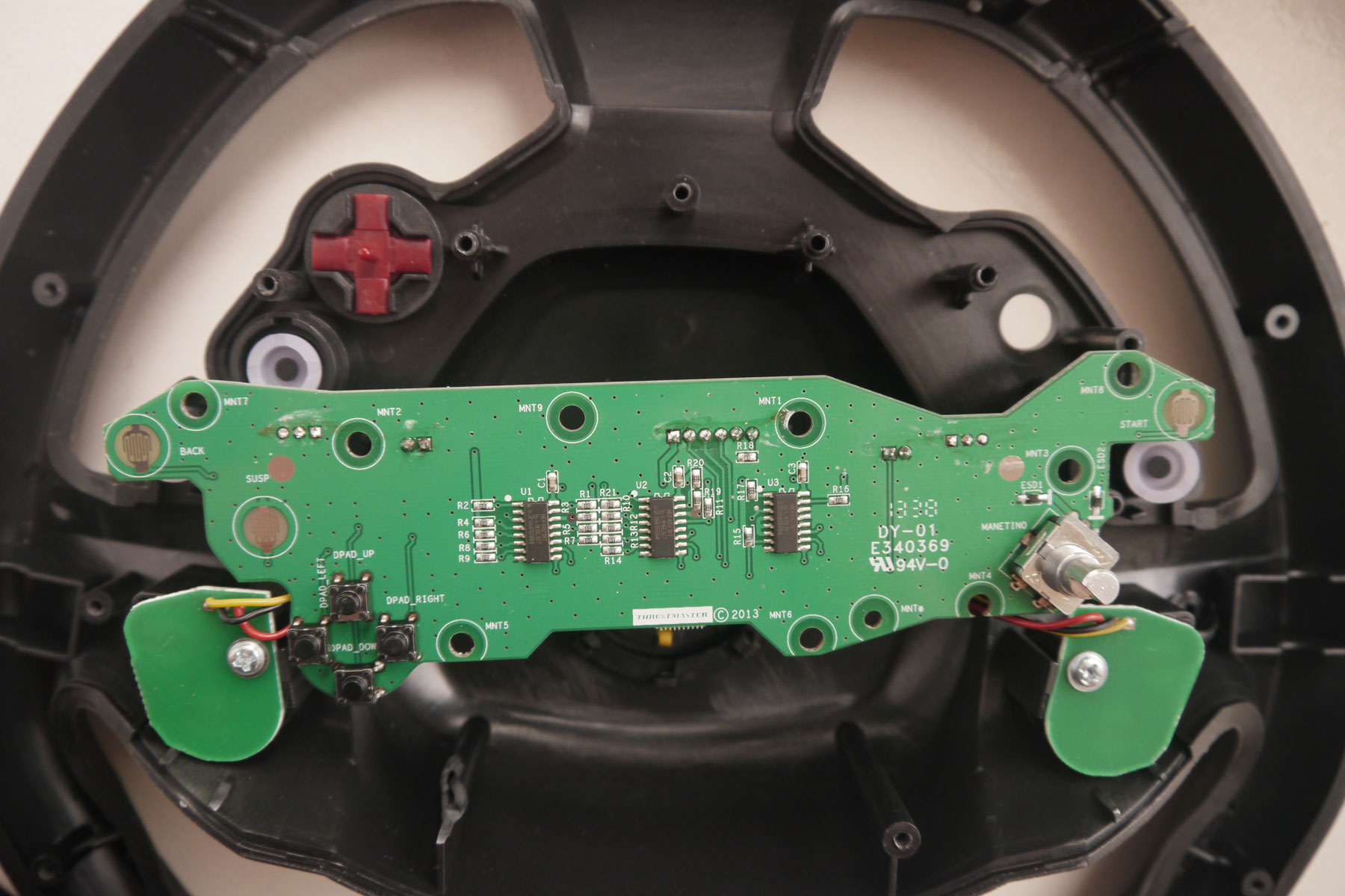
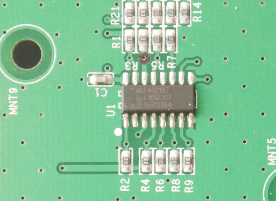
Hehehehe, see – there are 3 parallel-in-serial-out (PISO) shift registers inside (HEF4021BT – data sheet). Each has 8 inputs and a serial out. Totally 24 inputs and one output.
If we had 1 shift register, we could connect 8 buttons to it. If we had 2 shift registers – 16 buttons. But as far as this wheel has 17 buttons, we expected to see 3 of them inside, and we were right :) Time to read the data!
Thrustmaster TX RW wheel cable pinout (and T300/T500 I think)
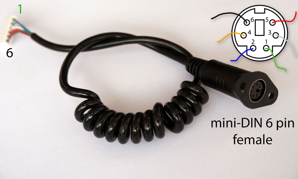
There’s a 6-pin header on the board, and a 6-wire cable (6 pins to round mini-DIN 6 Male – also called PS/2 male connector – can be found inside the wheel, and mini-DIN 6 female inside the wheelbase)
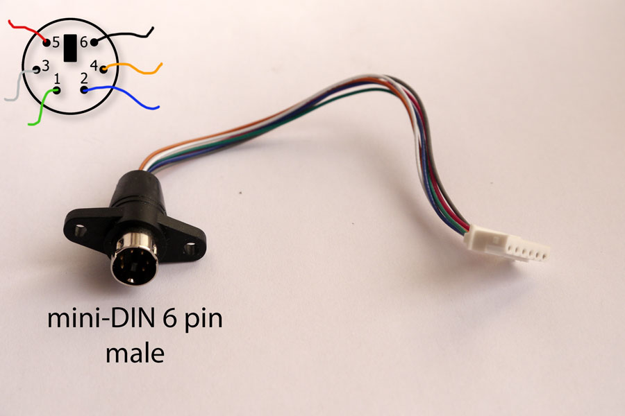
- Green – not used (connected to GND via 100k resistor, may be reserved for MOSI?)
- Blue – GND (ground)
- White – MISO (master-in-serial-out, this is a serial data line from wheel to base)
- Orange – SS (slave select, also called PL – parallel load)
- Red – SCK (sync clock impulses, each time pulse comes, shift register outputs 1 bit)
- Black +VCC (Arduino Uno uses +5V, wheelbase uses +3.3V – remember for future!)
On Arduino Uno side it must be connected as follows:
- Green -> not used (or can be connected to arduino MOSI pin 11)
- Blue - GND -> arduino uno GND pin
- White - MISO -> arduino uno pin 12
- Orange – SS -> arduino uno pin 7
- Red – SCK -> arduino uno pin 13
- Black +VCC -> arduino +5V pin
Here’s a tx_rw_wheel_reader.ino sketch source code (with my comments), that reads 3 bytes (you can change that to 8 bytes if you’re reading F1 wheel) via SPI serial protocol from the wheel – each second and outputs them as bits to serial monitor. By pressing the buttons is’t possible to determine the data format.
UPD 2018-03-09 - got a feedback, that old reader doesn’t work with Ferrari GTE Challenge wheel. Managed to fix it – here you are ferrari_gte_challenge_reader.ino (might also work with newer rims, all wiring is the same, just SPI setup is different).
/* This sketch provided "AS IS" under the BSD New license.
http://opensource.org/licenses/BSD-3-Clause
April 2015 © blog@rr-m.org

download tx_rw_wheel_reader.ino above - it has more comments */
#include <SPI.h>

const int slaveSelectPin = 7;

void setup() {
 Serial.begin(9600);
 SPCR |= _BV(CPHA);
 SPCR |= _BV(CPOL);
 SPI.begin();
 pinMode(slaveSelectPin, OUTPUT);
}

void loop() {
 // tell the wheel, that we gonna read the data now
 digitalWrite(slaveSelectPin, LOW);

 // read 3 bytes and output them to Arduino Serial monitor
 // as binaries 11000001 11111111 11111111
 // last 17 bits are buttons. 1 - released, 0 - pressed.
 for(int i=1; i<=3; i++) {
   printBinary(SPI.transfer(0x00));
 }
 Serial.println();

 // release the wheel
 digitalWrite(slaveSelectPin, HIGH);

 // wait 1 second, then read data from wheel again
 delay(1000);
}

// print byte as binary, zero padded if needed
// "127" -> "01111111"
void printBinary(byte data) {
 for(int i=7; i>0; i--) {
   if (data >> i == 0) {
     Serial.print("0");
   } else {
     break;
   }
 }
 Serial.print(data,BIN);
 Serial.print(" ");
}
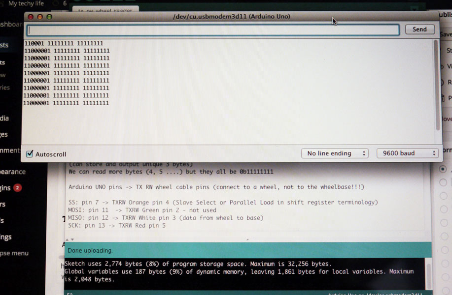
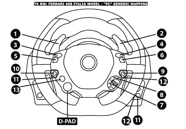
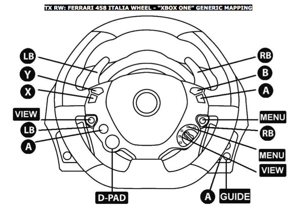
TX RW Ferrari 458 Italia data format and button mapping
All buttons released:
byte 1 byte2 byte3
11000001 11111111 11111111
Look, last 17 bits are our 17 buttons. 1 = released, 0 = pressed. First 7 bits are constants, may be they encode the wheel type? TX RW base supports 458 Italia wheel, F1 wheel and Ferrari GT wheel. Actually, I tried setting all first 7 bits to “1″, wheelbase still recognizes that as default Ferrari 458 wheel – will be shown in part 2.
Byte 1 (bits 7 to 0)
- 1 – constant
- 1 - constant
- 0 - constant
- 0 - constant
- 0 - constant
- 0 - constant
- 0 - constant
- 1 – Gear Up (button 2 = R_Pad)
Byte 2 (7 -> 0)
- 1 – A (button 6)
- 1 – B (button 4)
- 1 – RS (button 12)
- 1 – Menu (button 9, also named Start, it’s under A)
- 1 – Gear Down (button 1 = L_Pad)
- 1 – X (button 5)
- 1 – Manettino CCW (button 7, View)
- 1 – Manettino CW (button 8, Menu)
Byte 3 (7 -> 0)
- 1 – Suspend (button 13, above red D_Pad)
- 1 – Y (button 3)
- 1 – LS (button 11)
- 1 – View (button 10, also named Back – it’s under X)
- 1 – D-Pad Down
- 1 - D-Pad Right
- 1 - D-Pad Left
- 1 - D-Pad Up
458 Italia wheel and Arduino – video demonstration
The next time we’ll be connecting Arduino to the TX RW wheelbase and will try to emulate our custom buttons.
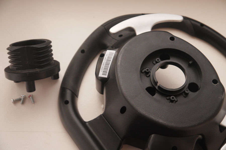
Note regarding the quick-release adapters
Threaded piece can be unscrewed and then mounted to a slim quick-release adapter (shown on video, really wasn’t too hard – added a piece of textolite with 6 holes). For those, who also want to attach a different wheel – probably you don’t need to buy a DSD T500 adapter for a start – just adapt the original one :)
Useful links
- tx_rw_wheel_reader.ino (ver 1.01 – 2015-07-17) – sketch source code for Arduino IDE
- ferrari_gte_challenge_reader.ino (2018-03-09) – another reader sketch for newer rims
- Shift registers explained – another great video
- Thrustmaster button mappings (documentation at official support site)
- The SPI of the AVR – SPI serial protocol explained
- Master-Slave SPI Arduino samples
- 8bit console joystick and Arduino
Comments
Comment on youtube or email me directly, please.