Purpose of this article – connecting Arduino board to a Thrustmaster TX RW wheelbase and emulating button presses. This trick will allow to replace the stock “plasticky” wheel (altogether with electronics) with some real racing wheel with buttons + arduino as a button controller.
Tools required
- Thrustmaster TX RW wheelbase (or T500/T300)
- Arduino board (3.3V version is better, but 5V should also work)
- Push buttons (mine are without fixation) and wires
- PC with installed TX RW drivers – to monitor button presses in Thrustmaster panel
Cable pinout
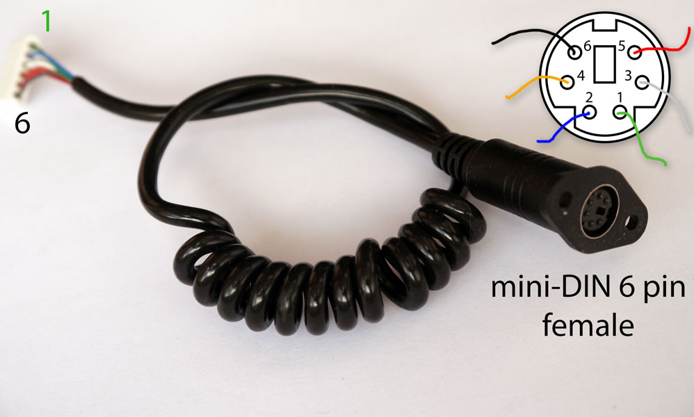
- Green – not used
- Blue – GND (ground)
- White – MISO (master-in-serial-out, this is a serial data line from arduino to base)
- Orange – SS (slave select, also called PL – parallel load)
- Red – SCK (sync clock impulses, each time pulse comes, 1 bit is sent)
- Black +VCC (wheelbase uses +3.3V, all logic levels also 0V or 3.3V)
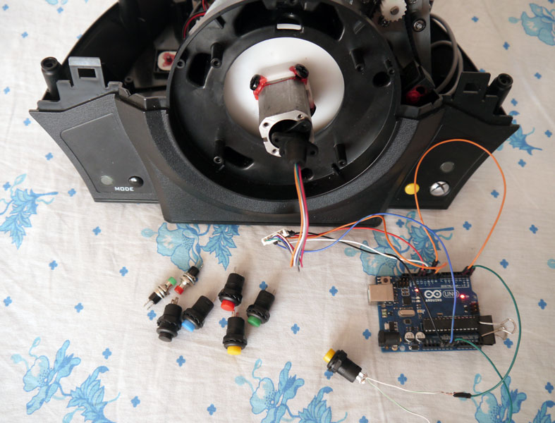
Thrustmaster TX RW wheelbase to Arduino Uno wiring
IMO it’s also valid for T300/T500 wheelbases (because F1 wheel is compatible with all bases -> they use the same connection). In this experiment wheelbase is a master device, arduino is a slave.
- Green -> not used
- Blue - GND -> arduino uno GND pin
- White - MISO -> pin 12
- Orange – SS -> pin 10 + pin 2
- Red – SCK -> pin 13
- Black +VCC -> arduino +VCC (+5V socket - that means we’re powering up Arduino from +3.3V line that wheelbase provides. USB and external power supplies must be disconnected from Arduino)
Orange line – yup, it’s connected to both pins 10 and 2. Why? There’s no SPI Slave implementation in Arduino framework, so pin 10 (slave select) alone is not enough. Additional pin 2 (interrupt 0) is needed to determine the start of a data transfer (we use interrupt routine for data re-initialization). Alternatively pin 3 (interrupt 1) can be used.
One more trick is a Power Source. There are two types of Arduinos – 5volts revision and 3.3volts revision. This not only controls the voltage required by onboard microchip, but (more important!) the logic levels, used for data transfer. Data inside computers is transferred as zeroes and ones – 110110010101…. Binary 0 is around 0V, but binary 1 can be either represented by +3.3V or +5V – depending on how you powered it.
TX RW wheelbase uses 3.3V logic levels. My Arduino Uno by default requires 5V (when powered from a USB cable, but also starts at a lower voltage). Solution – disconnect all power supplies from arduino (including usb) and power it up directly from a wheelbase (black wire +3.3V). Or there’s a How-To convert Arduino Uno to 3.3V article. Or just get a 3.3V factory-made revision – if you want both to play with a wheelbase, buttons and to have a USB debugging/serial monitor open in *ino IDE.
Push buttons can be connected to any other free pins left: 0,1,3-9, A0-A5. Push buttons have 2 pins of course. First pin connects to Arduino, seconds – to the ground. Released button encodes 1, pressed – 0 (grounded signal).
Source code
Download tx_rw_ferrari_458_wheel_emu_16buttons.ino sketch with comments.
/* This sketch provided "AS IS" under the BSD New license.

http://opensource.org/licenses/BSD-3-Clause

April 2015 © blog@rr-m.org

Full version with comments can be downloaded above -
tx_rw_ferrari_458_wheel_emu_16buttons.ino */
byte wheelState [8];
volatile byte pos;

void setup (void) {
 DDRB |= B00001011;  // pins 8,9,11 - inputs with a pull-up to +VCC
 PORTB |= B00001011;

 DDRC |= B00111111;  // pins 14-19 (A0 - A5) also inputs
 PORTC |= B00111111; // pulled-up to +VCC via internal resistors

 DDRD |= B11111011;  // digital pins 0,1,3,4,5,6,7 used as inputs
 PORTD |= B11111011; // pulled-up to +VCC via internal resistors

 wheelState[0] = B11000001; // 458 Italia Wheel first data byte
 wheelState[1] = B11111111; // second data byte - buttons
 wheelState[2] = B11111111; // third data byte - buttons
 wheelState[3] = B11111111; // this and below
 wheelState[4] = B11111111; // are not used
 wheelState[5] = B11111111; // but wheelbase reads all 8 bytes...
 wheelState[6] = B11111111;
 wheelState[7] = B11111111;

 pinMode(MISO, OUTPUT); // arduino is a slave device
 SPCR |= _BV(SPE);      // turn on SPI in slave mode
 SPCR |= _BV(SPIE);     // turn on interrupts

 // interrupt for SS rising edge.
 // Arduino Uno Pin10 must be also connected to Pin2!!!
 attachInterrupt(0, ss_rising, RISING);
}

// Interrupt0 (external, pin 2) - prepare to start the transfer
void ss_rising () {
 SPDR = wheelState[0]; // load first byte into SPI data register
 pos = 1;
}

// SPI interrupt routine
ISR (SPI_STC_vect) {
 SPDR = wheelState[pos++]; // load the next byte to SPI register
}

void loop() {
 // scan the button presses and save that to wheelState array.
 // Data transfer to wheelbase is interrupt-driven above.

 // take bit 0 from PORTB - TX RW byte1
 wheelState[0] = (PINB & B00000001) | B11000000;
 // take bit 1 from PORTB + the rest from PORTD B11111x11
 wheelState[1] = ((PINB & B00000010) << 1) | (PIND & B11111011);
 // take bit 3 from PORTB + bits 0-5 from PORTC
 wheelState[2] = ((PINB & B00001000) << 3) | (PINC & B00111111) | B10000000;
}
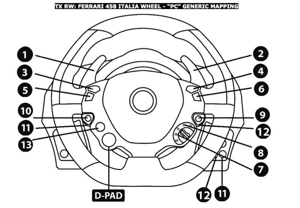
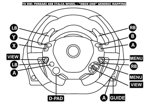
Thrustmaster TX RW data format and button mapping
As we saw in part 1, 458 Italia wheel has three 8bit registers inside – so it can store 3 bytes of data (state of 3×8 = 24 buttons max, wheel has 17 buttons). But, while communicating with a wheelbase I noticed, that it always attempts to read 8 bytes (64 bits), not 3 as I expected. So, the first 3 bytes encode buttons, last 5 bytes just filled with ones. This is how the original wheel handles that – and we emulate that behavior in .ino sketch.
Byte 1 (bits 7 to 0)
- 1 – constant
- 1 - constant
- 0 - constant
- 0 - constant
- 0 - constant
- 0 - constant
- 0 - constant
- 1 - Gear Up (button 2 = R_Pad) -> Arduino digital pin 8 (portB bit0)
Byte 2 (7 -> 0)
- 1 - A (button 6) -> pin 7 (portD bit7)
- 1 - B (button 4) -> pin 6 (portD bit6)
- 1 - RS (button 12) -> pin 5 (portD bit5)
- 1 - Menu (button 9) -> pin 4 (portD bit4)
- 1 - Gear Down (button 1 = L_Pad)-> pin 3 (portD bit3)
- 1 - X (button 5) -> pin 9 (portB bit1)
- 1 - Manettino CCW (button 7, View) -> pin 1 (portD bit1) – if you don’t use UART TX
- 1 - Manettino CW (button 8, Menu) -> pin 0 (portD bit0) - if you don’t use UART RX
Byte 3 (7 -> 0)
- 1 - Suspend (button 13, above red D_Pad) -> hey, not enough free pins left
- 1 - Y (button 3) -> pin 11 (portB bit3)
- 1 - LS (button 11) -> pin A5 (portC bit5)
- 1 - View (button 10) -> pin A4 (portC bit4)
- 1 - D-Pad Down -> pin A3 (portC bit3)
- 1 - D-Pad Right -> pin A2 (portC bit2)
- 1 - D-Pad Left -> pin A1 (portC bit1)
- 1 - D-Pad Up -> pin A0 (portC bit0)
TX RW wheelbase and arduino – button emulation – video demo
Useful links
- tx_rw_ferrari_458_wheel_emu_16buttons-1.02.zip (2020-05-06, pins config bugfix)
- tx_rw_ferrari_458_wheel_emu_16buttons-1.01.zip (old sketch)
- Master-Slave SPI Arduino samples
-
Hacking a Thrustmaster TX RW gaming wheel with Arduino Uno – part 1
Comments
Comment on youtube or email me directly, please.